Multi-Winding, Fault-Current-Limiting Design
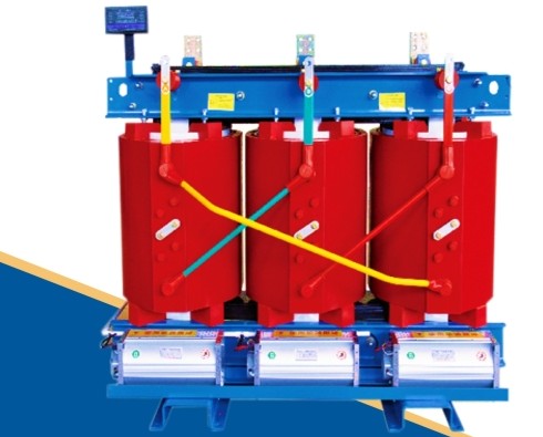
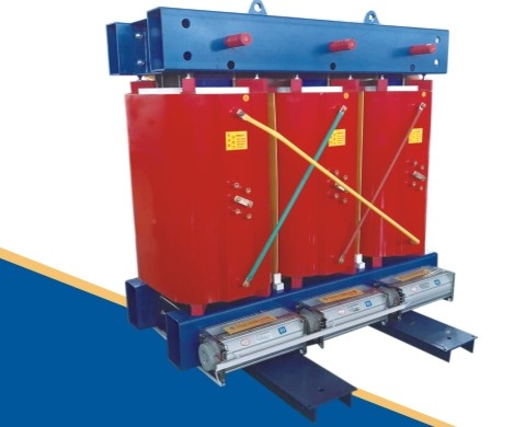
A multi-winding dry-type power transformer with one high-voltage winding and two or more low-voltage windings of equal voltage and capacity per phase. The manufacturer explicitly designates this model as suitable for new energy generation and energy storage power plant scenarios, where independent branches can carry separate loads or power sources while fault current between branches is limited.
Manufacturer-stated characteristics of the split dry-type transformer platform.
Each phase has one high-voltage winding and two or more low-voltage windings of equal voltage and capacity, with normal energy transmission occurring only between the HV winding and each LV branch.
In case of a fault, the split design acts to limit short-circuit current. Impedance between split branches is relatively large, while impedance between split and unsplit windings stays the same.
Branches of equal capacity and equal or close rated voltage can operate individually or in parallel and can bear the same or different loads.
When a load or power source connected to one low-voltage winding fails, the remaining low-voltage windings can still operate normally — the manufacturer highlights high reliability and a long service life for this platform.
The manufacturer's split-winding documentation we reviewed describes construction and behavior in detail but does not include a published rated-capacity/loss/impedance table (unlike the SCB and SCBH series). Fields below are marked where no verifiable source data exists — these are engineered per project.
| Configuration | 1 HV winding + 2 or more LV windings per phase, equal voltage & capacity |
|---|---|
| Energy Transmission Path | Normal transmission only between HV winding and each LV winding |
| LV-to-LV Electrical Connection | None — LV windings are not electrically connected to each other |
| Magnetic Coupling (between LV branches) | Relatively weak |
| Impedance (split branch to split branch) | Relatively large |
| Impedance (split to unsplit winding) | Same as standard (non-split) winding impedance |
| Fault Behavior | Limits short-circuit current between branches |
| Branch Operating Modes | Individual or parallel; same or different loads per branch |
| Branch Failure Isolation | A load/source failure on one LV branch does not stop the other branches operating |
| Protection Level | Configurable depending on installation environment |
| Insulation Process | [DATA REQUIRED] — likely epoxy resin vacuum pouring per the manufacturer's general dry-type platform, not separately confirmed for this model |
| Rated Capacity Range | [DATA REQUIRED] |
| Rated Voltage Combinations | [DATA REQUIRED] |
| No-Load Loss / Load Loss | [DATA REQUIRED] |
| Short-Circuit Impedance | [DATA REQUIRED] |
| Vector Group | [DATA REQUIRED] |
| Protection Rating (IP) | [DATA REQUIRED] |
| Warranty | [DATA REQUIRED] |
The manufacturer's own designated use case, directly quoted.
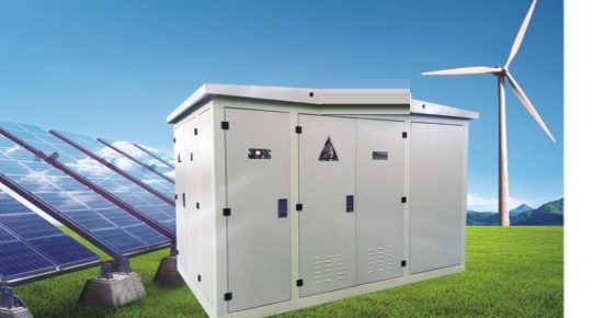
"Suitable for new energy generation and energy storage power plant scenarios" — the manufacturer's stated application for this model, making it a natural fit for multi-inverter PV collection points.
Multiple PCS/BESS racks can each connect to an isolated low-voltage branch, so a fault on one storage unit doesn't take down the whole collection point.
Branches with equal or close rated voltage and capacity can run individually or in parallel, suiting sites that combine multiple inverters, strings or storage units behind one step-up point.
Answers sourced from the manufacturer's split-winding documentation.
Other models worth considering for your project.
Send your required HV/LV voltages, number of branches and load profile. We respond with an engineered specification and FOB Shanghai pricing within 24 hours.